
MBES and the IHO SP44 Standards for Hydrographic Surveys
The International Hydrographic Organisation, based in Monaco, published the 5th edition of Special Publication No 44 Standards for Hydrographic Surveys in February 2008. SP44 sets forth the minimum standards for survey accuracy.
By 2008, multibeam echosounders had been well established as standard equipment for hydrographic survey. In that regard, SP44 is specific to hydrographic surveying — it contains nothing specific to multibeam echosounders. Rather, SP44 is a standard developed by the IHO ‘to help improve the safety of navigation.’ SP44 concerns itself with depth accuracy. However, a multibeam echosounder does not measure depth; it measures range and bearing to the seafloor.
‘To be compliant with an S-44 Order a survey must be compliant with ALL (sic) specifications for that order included in these Standards.’ (IHO Standard for Hydrographic Surveys (S-44) 5th Edition February 2008, pg 3, International Hydrographic Bureau, Monaco)
When a manufacturer states that a multibeam echosounder meets IHO SP44 or a client states a multibeam echosounder must meet IHO SP44 on a project, they may not understand the specifics of IHO SP44. SP44 looks at the total survey system:
“It is also important to note that the adequacy of a survey is the end product of the entire survey system and processes used during its collection.’ Further: ‘All components and their combination (sic) must be capable of providing data to the required standard.” (Ibid.)
What is the survey system comprised of (at a minimum)?
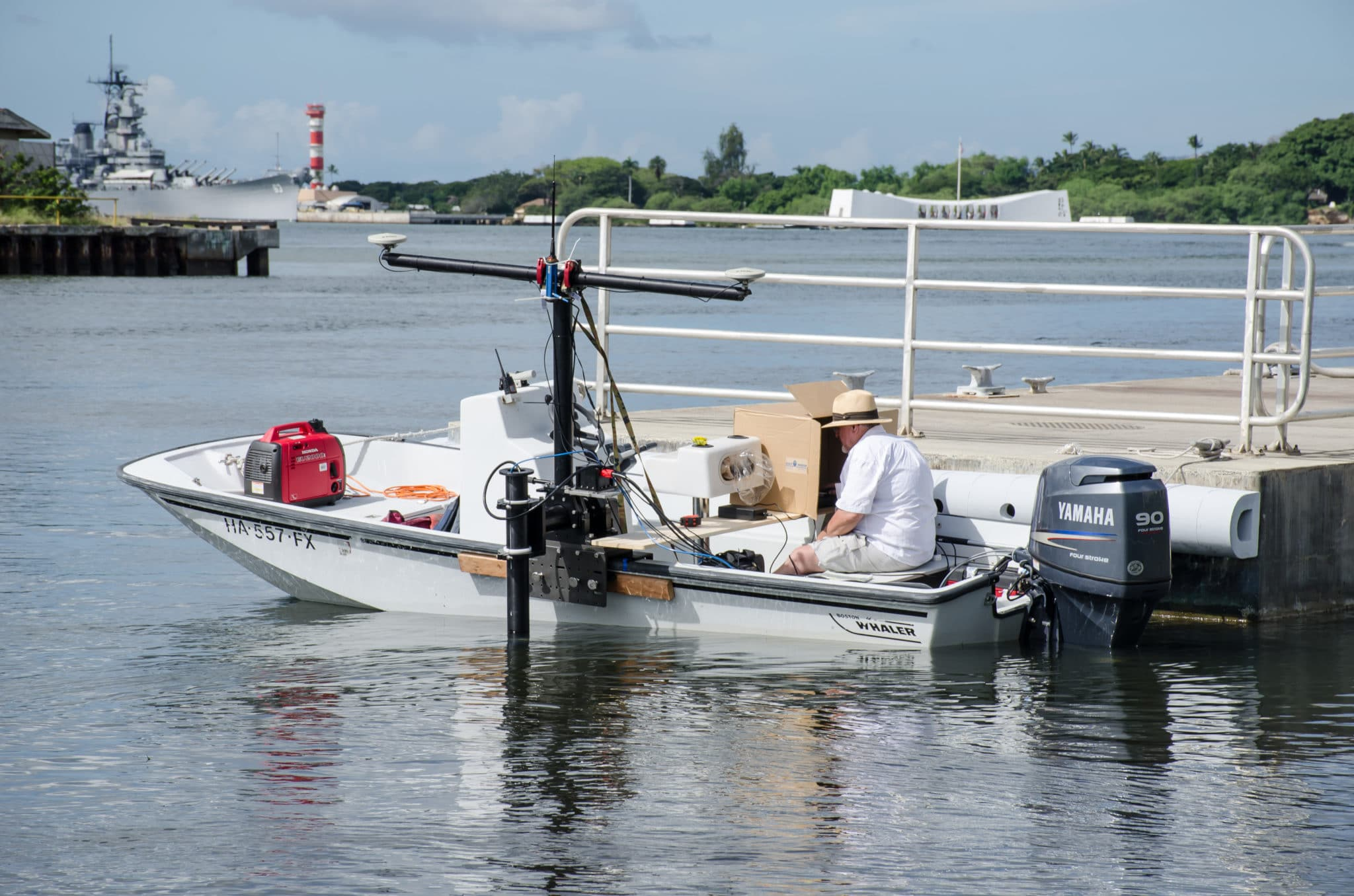
- Proper survey vessel
- Positioning system
- Motion sensor
- Aligned with axes of vessel
- Heave bandwidth adjusted properly
- Heading sensor
- Aligned with the centerline of the vessel
- Multibeam echosounder
- Properly mounted; if on a pole, there is no flexing or vibration
- Properly calibrated (Patch test)
- Operated properly
- Sound velocity profiler
- Calibrated
- Sufficient casts
- Tide gauge
- Proximity to the survey area
- Offset measurements
- Surveyed in using land survey techniques preferred
- Data collection and processing software
- Software set up correctly including timing control
- Software tools/windows enabled for quality control
- Skilled surveyors
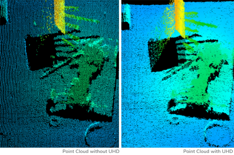
As the list above shows, the multibeam is approximately 1/10 of the entire survey system, as used in IHO SP44. The depth computation relies on the other 9/10 of the survey system along with the multibeam echosounder. The multibeam echosounder provides a range and bearing to points on the seafloor. The data collection/processing software receives the range and bearing data along with position, heading, and motion data, makes offset adjustment, and applies refraction corrections and tidal corrections to produce a depth. However, as an example, if the multibeam is mounted using a bamboo pole that wobbles, no matter how good that multibeam might be, no matter how good the other sensors are, the range and bearing data would be inaccurate due to pole wobble. Or, if the sound velocity profiler is out of calibration, the refraction corrections would be inaccurate, causing erroneous depths. These few considerations illustrate how the entire survey system must be evaluated for IHO SP44 order survey compliance.
Compliance with IHO SP44 Special Order (or Order 1a, 1b, or 2) can be proven for a survey system comprised of a multibeam echosounder by performing a set IHO survey for that specific vessel and that specific survey system and setup. However, changing any component would invalidate compliance.
Another aspect of the IHO SP44 standards is the horizontal uncertainty (2ẟ) that is allowed: 2 meters. If the IHO standard allows for a horizontal position error of this magnitude, how accurately is the depth positioned on the seafloor?
Feature Detection: IHO SP44 Special Order calls for the system to detect a 1-meter cubic feature. What the IHO SP44 does not state, however, is what constitutes detection. How many soundings determine detection?
There are other survey standards that better address the modern-day multibeam survey, such as the LINZ produced Contract Specifications for Hydrographic Surveys (Version 1.3; 2016).
The main point is that there are many components in a survey system, and it is the survey system that will determine compliance with IHO SP44 survey order specifications. One component of the survey system cannot be singled out, such as the multibeam echosounder.